Fire Alarms
- services
- fire alarms
Remote Alarm Monitoring
It is not always possible for you to fully monitor your security systems which makes it important to know that someone else is. Xcell Misting offer remote monitoring of alarms for key holders that do not operate 24/7. Your alarm will be set to notify the central monitoring system when triggered, and we will attend to the problem.

M Fire Alarm System
Manual systems e.g. hand bells, gongs etc, may be purely manual or manual electric, the latter may have call points and sounders. They rely on the occupants of the building discovering the fire and acting to warn others by operating the system. Such systems form the basic requirement for places of employment with no sleeping risk.
P1 Fire Alarm System
The system is installed throughout the building – the objective being to call the fire brigade as early as possible to ensure that any damage caused by fire is minimised. Small low risk areas can be excluded, such as toilets and cupboards less than 1m².

P2 Fire Alarm System
Detection should be provided in parts of the building where the risk of ignition is high and/or the contents are particularly valuable. Category 2 systems provide fire detection in specified parts of the building where there is either high risk or where business disruption must be minimised.

L1 Fire Alarm System
A category L1 system is designed for the protection of life, which has automatic detectors installed throughout all areas of the building (including roof spaces and voids) with the aim of providing the earliest possible warning. A Category L1 system is likely to be appropriate for the majority of residential care premises. In practice, detectors should be placed in nearly all spaces and voids. With category 1 systems, the whole of a building is covered apart from minor exceptions.
L2 Fire Alarm System
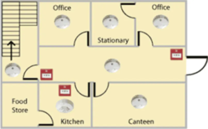
A category L2 system designed for the protection of life, which has automatic detectors installed in escape routes, rooms adjoining escape routes and high hazard rooms. In a medium sized premises (sleeping no more than ten residents) a category L2 system is ideal. These fire alarm systems are identical to an L3 system but with additional detection in an area where there is a high chance of ignition (e.g. kitchen) or where the risk to people is particularly increased (e.g. sleeping risk).

L3 Fire Alarm System
This category is designed to give early warning to everyone. Detectors should be placed in all escape routes and all rooms that open onto an escape route. Category 3 systems provide more extensive cover than category 4. The objective is to warn the occupants of the building early enough to ensure that all are able to exit the building before escape routes become impassable.

L4 Fire Alarm System
Category 4 systems cover escape routes and circulation areas only. Therefore, detectors will be placed in escape routes, although this may not be suitable depending on the risk assessment or if the size and complexity of a building is increased. Detectors might be sited in other areas of the building, but the objective is to protect the escape route.

L5 Fire Alarm System
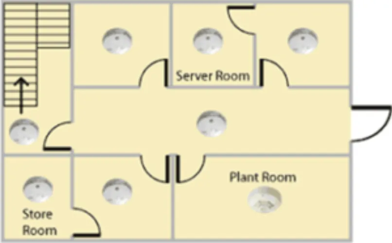
This is the ‘all other situations’ category e.g. computer rooms, which may be protected with an extinguishing system triggered by automatic detection. Category 5 systems are the ‘custom’ category and relate to some special requirement that cannot be covered by any other category.
Objectives of Servicing a Fire Alarm/Extinguishing Detection System
The following details the procedure to be followed for the routine periodic inspection and testing of a Fire Alarm System/Extinguishing System.
The procedure is a “General” procedure that is applicable to most installations. Where the system design or the procedure required deviate significantly from this procedure the deviations will be identified elsewhere (usually in the Schedule, special Instructions).
There are a few distinct types of Fire and Smoke detection systems: Conventional. (To include extinguishing systems) Analogue Addressable,
Radio Addressable & manual only
Typically, all systems will comprise of a control panel smoke, heat detectors, break glass units and sounders. The system may be linked via relays and interfaces to alert other systems, shut down plant and alert remote monitoring stations or release extinguishing gas.
Under the following headings there are lists of activities. The order of the list does not imply the order in which the actions will be carried out.
PRIOR TO SITE VISIT
The engineer will advise the client’s representative:
The date and time the service would take place, (if so required from client instructions). The engineer will ensure all necessary tools and access equipment are available.
UPON ARRIVAL AT SITE
The Engineer will check the RAMS and sign the form for approval
The Engineer will ask for the asbestos register. Check that the work area is free of asbestos. If in doubt stop work and contact the designated supervisor.
The engineer will observe all booking in and health and safety procedures.
The engineer will obtain authority from the client’s representative to isolate any interconnected devices, i.e. shut downs of computers etc. Authority will also be sought to test the audible and visual alarms. If the authority is not obtained the interconnection will not be tested and this will be noted on the inspection certificate.
The engineer will locate the systems logbook(s).
The engineer will inspect the logbook and discuss with the client’s representative the entries that need attention, i.e. outstanding remedial work etc.
If no logbook is available, one will be supplied complete with wall mounted document holder.
If the system is connected to a Central Monitoring Station then the Engineer will ask for the system to be put on test. If the site is under contract, then the engineer will check that the ‘Call Out’ sticker is prominently displayed.
QUARTERLY SERVICE
The service will be carried out to the requirements of BS5839: Part 1: 2017, as listed below. The engineer will therefore carry out the following operations:-
A visual inspection to check that structural or occupancy changes have not affected the requirement for Break Glass Units, Detectors and Sounders. Check charger voltage with and without batteries and adjust if necessary.
Check the batteries with a proprietary battery tester.
Check that there is a clear space of 750mm round each detector.
Check that there is a Break Glass Unit by each exit from the building, and that they are unobstructed.
Check that there is sufficient alarm audibility (65db throughout). If there is a doubt, then a separate audibility test will need to be carried out.
Simulate all fault conditions. The open circuit fault will be simulated by removing the end of line device (if accessible) or opening the circuit at any accessible position (if the end of line device is not accessible). The engineer will check that the correct indication and functions operate at the controls.
A minimum of one device (detector) on each zone shall be put into an alarm condition using smoke or heat. The engineer will check that the correct indication and functions operate at the Control Panel.
A minimum of 25% of smoke Detectors, Break Glass Units and 2% of Heat detectors will be tested.
All ancillary devices shall be operated and the engineer will check for the correct function. This includes links to a Central Monitoring Station in the form of a Digital Communicator or Redcare.
Any system items found to be faulty, outside normal operating parameters or date expired will be listed under the ‘Items Failed’ column. With the client’s permission these parts will be
changed and listed by part number and description in the ‘Items Replaced’ column of the Certificate of Inspection.
SPECIAL INSPECTION AND TESTING
WIRING CHECK
Subject to a separate agreement the engineer will strip down the system and carry out a “five yearly wiring check” in a; prescribed manor according to the IEE regulations.
AUDIBILITY TEST
Subject to a separate agreement the engineer will carry out an audibility test to ensure that there is 65db audibility throughout. A Minimum of 75db at the bed head is required for residential buildings.
UPON COMPLETION OF THE SERVICE
The engineer will contact the Central Station and take the system off test and confirm that the expected signals have been received.
The engineer will complete the logbook, including references to any deviations, recommendations, faults etc. The engineer will ensure the client’s representative understands the entries and will obtain the signature of the client’s representative against each entry.
The engineer shall provide a signed dated report of the inspection (certificate of inspection), including references to any deviations, faults and additional work carried out. The engineer will ensure the client’s representative understands the references and obtain the signature of the client’s representative against entry. If a recommendation is made which requires a quotation to be made, then this will be marked as ‘Recommendation made’. This will normally result in a quotation being issued about 2 weeks later.
DEFINITIONS
SITE
The client premises where the work is to be carried out.
CLIENTS REPRESENTATIVE
The responsible person nominated by the client.
LOGBOOK
A record kept by the user of all significant events involving the fire alarm system.
CERTIFICATE OF INSPECTION
The certificate issued by the engineer.
ACCESS EQUIPMENT
All platforms, hoists, lifts and scaffolding or other equipment to enable the engineer to carry out the specified work.